
ZX Spectrum Graphics Magic: The Basics Every Spectrum Fan Should Know
Hey friends! (Or just curious readers peeking under the hood of good old retro games).
My previous article on calculating angles with integers was well-received. Several people wrote to me, some asked questions, others offered their own algorithm variations, and it turns out there are quite a few ZX Spectrum programming enthusiasts – it’s fascinating, and that’s what all this is for!
In my new article, I wanted to talk in detail about drawing lines and other primitives on the Speccy, but I suddenly realized that some might not be familiar with how the Speccy’s screen is structured at all, and without that, it’s absolutely impossible to move forward. It’s like trying to build a house without knowing what a brick is made of or how to lay it!
So, let’s break down this, frankly, complex topic. We’ll figure out how the classic Spectrum draws things on the screen, and of course, we’ll draw something simple but enlightening! Get your virtual oscilloscopes and soldering irons ready (or just your emulators)!
Part 1: Screen Secrets: Why the Speccy Draws the Way It Does
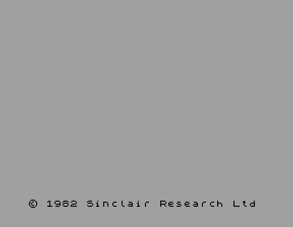
So, when we turn on our beloved Speccy, we see that magical black window in a white frame, with red lines flashing across it, and then everything turns white with text at the bottom. If we switch the screen background to black (for example, in BASIC with the command "PAPER 0: INK 7"), we’ll see a black field measuring 256 pixels horizontally and 192 pixels vertically. This is our main "canvas" for creativity!
It seems simple enough, right? It’s just a pixel grid, like in Paint! If you want to draw a dot at coordinates (X, Y), you just access the "cell" with those coordinates in video memory, put the desired color there, and you’re done.
But here’s the Spectrum’s first trick! Its video memory isn’t as straightforward as you might think. It’s divided into two large parts:
-
Pixel Area: This stores data on whether each specific pixel is on or off. "On" (value "1") means it’s drawn with the INK color; "off" (value "0") means it’s drawn with the PAPER color. Each pixel is represented by just one bit!
-
Attribute Area: This stores data on which INK color, which PAPER color, and what effects (BRIGHT/FLASH) will be used for a group of pixels.
The most important point: this "group of pixels" isn’t a single pixel! It’s a block measuring 8 pixels horizontally and 8 pixels vertically. So, the entire 256×192 screen is divided into a grid of such attribute blocks: 256 / 8 = 32 blocks horizontally and 192 / 8 = 24 blocks vertically. A total of 32 * 24 = 768 attribute blocks. In some literature, these "blocks" might be called "characters" or "squares."
For each such block (8×8 pixels), a separate attribute byte is stored in a distinct memory area. This byte contains information:
-
Lower 3 bits (0 to 2): INK color (one of 8 standard colors: 0 = black, 1 = blue, 2 = red, 3 = magenta, 4 = green, 5 = cyan, 6 = yellow, 7 = white).
-
Next 3 bits (3 to 5): PAPER color (also one of the same 8 colors).
-
Bit 6: BRIGHT flag (makes INK and PAPER colors brighter). It’s important to understand that both colors become brighter – both ink and paper – so we can’t draw, for example, dark red on bright white.
-
Bit 7: FLASH flag (makes the INK and PAPER colors of this block constantly swap places). This creates a fun hardware animation – the entire pixel block "flashes" at approximately 2 Hz. This hardware animation takes 0 CPU cycles and (proudly!) was therefore often used in early ZX Spectrum games.
Do you see the catch? Within one 8×8 block, all "on" pixels will be the same INK color, and all "off" pixels will be the same PAPER color, as defined by the attribute byte for that block. You cannot draw one pixel in an attribute block with red INK and a neighboring one with green INK! Both will use the color determined by that block’s attribute.
This leads to the famous "Attribute Clash" – when a moving sprite (image) larger than 8×8 pixels passes through blocks with different attributes, parts of the sprite suddenly change their colors because they fall under the influence of the attributes of the blocks they are in. This is a characteristic feature of the Spectrum that gave games a unique look (and developers a headache!).
So, to draw a colored pixel at coordinates (X, Y) on the Speccy, you need to do two things:
-
Find the byte in the pixel area of video memory that corresponds to this pixel, and set the appropriate bit.
-
Find the byte in the attribute area that corresponds to the 8×8 block containing this pixel (its coordinates will be (X/8, Y/8), rounded down), and set the desired INK/PAPER colors and BRIGHT/FLASH flags.
The trickiest part here is the first one! The pixel memory area is not simply laid out row by row. It’s cleverly intertwined to simplify the work of the television display circuit. But we’ll cover that in more detail in the next part.
First, let’s learn how to find the address and the correct bit for one pixel and try to "turn it on."
Part 2: Lighting a Star (Drawing a Dot)!
Imagine you want to draw just a single dot on the Speccy screen. Let’s say it’s at coordinates X=50, Y=50.
At first glance, it seems: well, the screen is 256×192. Each row is 256 pixels. Each pixel is 1 bit. So, a row occupies 256 / 8 = 32 bytes. The screen is 192 rows * 32 bytes/row = 6144 bytes. The address of point (X, Y) should be start_address + Y * 32 + X / 8, and the required bit in that byte is X % 8. Logical, right?
Not quite! The ZX Spectrum wouldn’t be itself if everything were so simple! Its video memory (pixel part) is structured very specifically to simplify the operation of the hardware video controller ULA (which, in essence, is very primitive there). Screen memory starts at address $4000 (16384 decimal). And from there, it doesn’t go sequentially row by row!
The address of the byte containing pixel (X, Y) is calculated by a rather tricky formula, but before I write it down, let’s do a thought experiment.
Imagine you’re moving from address $4000 downwards and filling all the pixels behind you (writing the value $FF to all traversed bytes). For the first 31 bytes, you’ll see the zero row filled from left to right. But as soon as you go beyond the right edge, you won’t land on row 1, but on row 8! That’s how an offset of +32 corresponds to row 8. If you continue, after another 32 bytes, you’ll appear on row 16. And so on, up to row 64 (in total, you’ll have to go through 256 (or $100) bytes. But contrary to expectations, you’ll then find yourself on row 1!
Wow! It turns out that to move down one row, we need to add +$100 to the address. It’s unknown why Sir Clive Sinclair chose this particular order, but it turned out to be very convenient for displaying simple characters that occupy exactly one pixel block! After all, increasing a two-byte register by $100 only requires one short assembly instruction, like INC H if the address is stored in the HL register.
This way, we’ll go through $800 bytes (2048 of them) and fill exactly one-third of the screen – the top 64 rows.
And only after that will we start filling the second third, and then the third third.
Does this remind you of anything? Yes, yes, we all remember how the splash screen of any game loads from cassette – with strange lines. That’s exactly it!
So, we can schematically draw the formula for calculating the byte address.
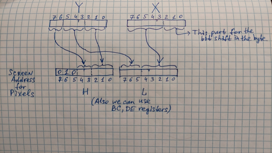
It shows that to shift down by 1 line, you need to add $0100; to shift by 8 lines, add $0020; and to shift by 64 lines, add $0800.
Here’s what the formula will look like in Javascript (I’ll use Javascript to prototype our ideas because it’s very simple and can be run right in the browser!):
Adr = 0x4000 + (Y & 0xc0 << 5) + (Y & 0x38 << 2) + (Y & 0x07 << 8) + (X & 0xF8 >> 3)
Well, by old tradition, let’s write the code for Z80 Asm too!
; Let X be in register L, and Y in register H.
; We'll assume that the value of Y is already within the valid range (0 to 191)
; and won't check it for speed.
; On exit, the address will be in HL.
; The procedure uses and "corrupts" registers A and B.
GetScrAddr
    ld a, $38
    and h   ; extract a small 3-bit piece from Y
    rlca
    rlca      ; shift it left by 2 bits
    ld b, a  ; and temporarily save it in B
    ld a, $f8  ; extract the upper 5 bits from X
    and l
    rrca       ; and shift it 3 bits to the right
    rrca
    rrca
    or b    ; combine with B
    ld l, a  ; L calculation is complete! Now calculate H
    ld a, $c0
    and h  ; extract the 2 most significant bits from Y
    rrca
    rrca
    rrca    ; shift them 3 bits to the right
    ld b, a  ; save temporarily in B
    ld a, $07 ; extract the 3 least significant bits from Y
    and h
    or b   ; no need to shift them - they are already in place. Just combine them with B
    or $40  ; and append $40 to get the address $4000-$57ff
    ld h, a   ; H is ready!
    ret
Phew! We exhaled. Now we know the byte address. But that’s not enough! This byte contains 8 pixels. Which one is ours? The desired pixel (X, Y) is bit number X % 8 (remainder of division by 8) (or X & $07) in that byte. Furthermore, bit 7 is the leftmost of the eight pixels, bit 0 is the rightmost. So, we need bit number 7 - (X & $07).
All that’s left is to "turn on" this bit, i.e., set it to 1, without touching the other 7 pixels in this byte. To do this, we read the byte from video memory, perform a bitwise OR (OR) operation with a mask in which only our desired bit is set, and write the result back. The mask for bit b is 1 << b. So, for bit 7 - (X & $07), the mask will be 1 << (7 - (X & $07)).
Now let’s try to calculate the address for X=50, Y=50 by hand:
Y = 50. In binary:00110010.X = 50. In binary:00110010.
Byte address calculation:
Y & $C0(00110010&11000000) =00000000. Shift << 5 = 0.Y & $38(00110010&00111000) =00110000(0x30). Shift << 2 =11000000(0xc0).Y & $07(00110010&00000111) =00000010(2). Shift << 8 =10 0000000(0x0200).X >> 3(00110010>> 3) =00000110(6).
Summing it all up, we get the address = $4000 (16384) + 0 + 192 + 512 + 6 = 16384 + 710 = 17094 ($42C6).
Required bit calculation:
X & $07(00110010&00000111) =00000010(2).- Required bit =
7 - 2 = 5. - Mask for bit 5:
1 << 5=00100000($20).
Now, to draw the point (50, 50), we need to:
- Read the byte at address $42C6 – but we can skip this step for simplicity if we have an empty screen.
- Perform a bitwise OR with the mask $20 (to set bit 5).
- Write the modified byte back to address $42C6.
What about the color? We haven’t set the color yet! For that, we need to access the attribute area.
The address of the attribute byte for point (X, Y) is much simpler to calculate:
Attribute_Address = $5800 + (Y >> 3) * 32 + (X >> 3)
For X=50, Y=50:
Y / 8(50 / 8 = 6 with remainder) = 6.X / 8(50 / 8 = 6 with remainder) = 6.
Attribute address = $5800 (22528) + 6 * 32 + 6 = 22528 + 192 + 6 = 22726 ($58C6).
At address $58C6 lies the attribute byte for the 8×8 pixel block that contains point (50, 50). If we want our point to be drawn bright red (BRIGHT=1, INK=2), and the background to be black (PAPER=0), this byte should be:
BRIGHT=1 (bit 6), FLASH=0 (bit 7), PAPER=0 (bits 3-5), INK=2 (bits 0-2).
Binary: 0 1 000 010 = %01000010 = $42.
So, to draw a bright red point (50, 50) on a black background:
- At address $58C6, write byte $42.
- At address $42C6, read the byte, perform OR with $20, write back.
And there’s our dot! Look at our drawing below: there’s a black square, and inside it, a tiny red dot!
You can view the code and experiment with it by clicking the icon in the corner of this drawing and then selecting "CODE".
Part 3: Bringing Bytes to Life: Drawing a Funny 8×8 Face
So, in the last part, we fought our way to understanding how to find the address of a single pixel in the Speccy’s tricky video memory and how to "light it up" by setting the right bit in the right byte at the right address. Phew! But an image isn’t just one dot; it’s many, many dots!
The most basic graphical primitive after a dot is, essentially, a character. On the Spectrum, characters (letters, numbers, symbols) have a standard size of 8 pixels wide and 8 pixels high. How are they stored? Very simply: each line of such a character is one byte!
Why? Because 8 pixels are exactly 8 bits. And a byte is 8 bits! So, the byte 10110010 means that in this character line, pixels at positions 7, 5, 4, and 1 are "on" (INK) (counting from left to right, from 7 to 0), and the rest are "off" (PAPER).
Bit: 7 6 5 4 3 2 1 0 (pixel position from left to right)
Byte: 1 0 1 1 0 0 1 0  ->  # . # # . . # .
So, our 8×8 character is stored as a sequence of eight bytes. The first byte is the top line of the character, the second is the next, and so on, until the eighth byte – the very bottom line.
We want to draw a funny face. Here’s its "matrix" of eight bytes:
$3c, $42, $81, $a5, $81, $99, $42, $3c
(Some people memorize poems and capital city names by heart; we, Speccy enthusiasts, have a special gift – we memorize numbers and codes. For example, I remember the exact bytes for drawing this face since 1993.)
Let’s convert these bytes to binary and see what they look like if we represent 1 as # (INK color) and 0 as . (PAPER color):
0x3c=00111100->..####..0x42=01000010->.#....#.0x81=10000001->#......#0xa5=10100101->#.#..#.#0x81=10000001->#......#0x99=10011001->#..##..#0x42=01000010->.#....#.0x3c=00111100->..####..
How do you draw such an 8×8 block on the screen, starting at coordinates (X, Y)?
We know how to find the byte address for pixel (X, Y). Let’s call it Base address. This is the address of the byte that will contain the first row of our face (0x3c). But where are the bytes for the subsequent rows (Y+1, Y+2, …, Y+7)?
As we found out in the last part, due to the Speccy’s tricky video memory arrangement, this is not true! The byte addresses for consecutive rows (within one 8-row Y-block) are 256 bytes apart.
(Of course, this is true as long as Y and Y+7 are within the same 8-row block along the Y-axis, i.e., Y % 8 + 7 < 8. But for drawing an 8×8 character, we usually choose Y such that Y is a multiple of 8, for example Y=0, 8, 16… In this case, the entire character fits precisely into one such 8-row Y-block, and this 256-byte step rule applies to all 8 rows of the character).
Besides pixel bytes, we naturally also need an attribute! Our entire 8×8 character fits perfectly into one attribute block. This means all pixels of this face will use the same INK/PAPER colors and the same BRIGHT/FLASH flags that we write into the attribute byte for the block containing (X, Y). We also know how to calculate the address of this attribute byte from the previous part: $5800 + (Y / 8) * 32 + (X / 8).
So, the algorithm for drawing an 8×8 character/face at coordinates (X, Y) is as follows:
- Choose the desired attribute byte (e.g., blue INK on white PAPER =
%0 0 111 001= $39). - Calculate the attribute byte address for block (X, Y):
AttrAddress(X, Y). - Write the chosen attribute byte to address
AttrAddress(X, Y). - Calculate the base pixel byte address for (X, Y): for this, we will use X and Y rounded to multiples of 8, e.g., X = 48 and Y = 48.
- Write the 8 bytes of our image sequentially, incrementing the address by $100.
Let’s look at the code.
// This is the array where we store the "graphic data" of our smiley
const smiley_data = [
  0x3c, 0x42, 0x81, 0xa5, 0x81, 0x99, 0x42, 0x3c
];

let adr = 0x40c6;  // This is the address of the top (zero) byte of the location where we intend to output the smiley
for (let i = 0; i < 8; i ++) {
    ram[adr] = smiley_data[i];   // In a loop, transfer data from the array to video memory 8 times
    adr = adr + 0x100;   // move to the next line
}

ram[0x58c6] = 0x39;  // Attribute address for our face and its color
And traditionally, the Asm code:
DrawSmile:
    ld hl, $40c6     ; HL - address in video RAM
    ld de, .smile_data   ; DE points to the smiley data array
    ld b, 8    ; B will count down from 8
.loop
    ld a, (de)    ; get byte from DE
    ld (hl), a     ; and put it into HL
    inc de        ; move to the next smiley byte
    inc h          ; move down a line on the screen (this is equivalent to HL = HL + $0100, only faster, because L doesn't change, and H increments by 1)
    djnz .loop  ; this loops our program 8 times, to repeat the same for all 8 bytes
    ret
.smile_data
    db $3c, $42, $81, $a5, $81, $99, $42, $3c
So, we’ve learned how to take 8 bytes of data representing an 8×8 pixel image, find the correct attribute block, write the color there, and most importantly, write these 8 bytes to the correct locations in pixel memory, accounting for the 256-byte step between lines. This is a very important skill for anyone who wants to draw anything more complex than a single dot on the Spectrum!
In the next part, we’ll delve into how to optimize pixel address calculation so that we don’t have to perform all those complex bitwise operations "from scratch" every time.
Part 4: Breaking Through Memory: Optimizing Address Calculation
We’ve learned how to find the address of a single byte of pixel memory for point (X, Y), the address of the attribute byte for block (X, Y), and even how to write 8 bytes for a character, knowing that rows are 256 bytes apart. That’s great! But if we look closely at the pixel byte address calculation formula:
Address = $4000 + ((Y & $C0) << 5) + ((Y & $38) << 2) + ((Y & $07) << 8) + (X >> 3)
It’s clear that it’s quite cumbersome. Every time, for each point, for each primitive byte (line, sprite), performing all these bitwise operations, shifts, and additions on the Z80 will consume precious CPU time. If we want to draw fast-moving objects or many details, we need something quicker!
As usual, there are several optimization paths.
Method 1: Moving Gradually (Incremental Calculation)
What if, instead of calculating the address from scratch $4000 every time, we move from an already known address to an adjacent one? We’ve already figured out how to move down one line – just add $100! But this won’t work everywhere. When we reach the 7th line in an 8*8 pixel block, we’ll have to go back $700 (7 lines up) and then increase the address by $20! But let’s start from simple to complex.
-
Shift pixel right (+1 to X): If it’s about outputting a single pixel, we simply shift the byte mask by 1 bit to the right. For example, if we had a mask $20 for coordinate X=50, to print a point with coordinates X=51, we just need to rotate the byte 1 bit to the right; the video RAM address doesn’t even change! However, if our point is already pressed against the right edge of the byte (value $01), then we’ll still have to increment the address by 1. But that’s so simple!
-
Shift pixel left (-1 to X): This is completely analogous to shifting right, but in reverse. If the bit is not pressed against the left edge (value not $80), then shift the byte left by 1 bit. Otherwise, decrement the video memory address.
-
Shift line down (+1 to Y): This is where the difficulties begin! If we are at
Addr(X, Y)and want to go toAddr(X, Y+1). We already know that bytes of consecutive rows within one 8-row block are 256 bytes apart. So, ifY % 8is not equal to 7, the address of the next row is simplyAddr(X, Y) + 256! This is a fast addition on the Z80 (ADD HL, $0100).
But ifY % 8is equal to 7 (we are in the last row of an 8-row block), moving to Y+1 means crossing a block boundary. And here, the offset is no longer 256! It depends on which block and which "third" of the screen we were in. Calculating the address for (X, Y+1) after crossing the boundary will require either a complete recalculation of the address from scratch using the complex formula, or another trick. -
Shift line up (-1 to Y): Similarly, if
Y % 8is not equal to 0, the address of the previous row isAddr(X, Y) - 256. IfY % 8is equal to 0 (we are in the first row of an 8-row block), we cross the boundary again and a complete recalculation or trick is needed. I note that moving up when drawing graphics on the ZX Spectrum is rarely used, but it also has its place.
Here’s the trick used. We can check the current address and, based on it, deduce how much to add to the address. This algorithm is also widely known as the "LINEDOWN_HL Algorithm".
; Input: HL = Current address from which we want to move to the next line
; Output: HL = Address of the next line on the screen
; Uses: register A.
LineDown:
    inc h    ; try moving down 1 line (HL = HL + $0100 conceptually)
    ld a, h
    and 7    ; check that we haven't jumped over an 8x8 block boundary (e.g., was $47xx, became $48xx)
    ret nz    ; if the lower 3 bits are not zero, then everything is within the block, finished.

    ld a, l    ; if yes, then we need to correct, because we clearly landed in the wrong place
    add a, 32    ; shift by 32 bytes (to land on the next line within the screen segment) - e.g., was $48e5, became $4805 with a carry
    ld l, a
    ret c    ; if an overflow occurred during summation, it means we correctly landed in the next third ($4805 - that's exactly the case)

    ld a, h    ; Well, if not, it means we overshot and need to correct H - return to the previous third (e.g., was $47c5, mistakenly
    sub 8    ; first landed in $48c5, then in $48e5 - no carry.
    ld h, a   ; Decrease H by 8 to get $40e5 - the correct address.

    ret
But all this takes time. Calculating the initial address, then moving down to draw each byte… can’t it be faster?
Yes, it can! And SIGNIFICANTLY FASTER.
Method 2: All-Purpose Reference (Table Method)
Probably the most popular way to quickly find the address for any coordinates (X, Y) is to use a pre-calculated table.
-
Row Address Table: Create a table in memory (an array of 16-bit words) that stores the address of the first byte (
X=0) for each Y (from 0 to 191). The table will have 192 elements, each 2 bytes long (an address occupies 16 bits). Total size: 192 * 2 = 384 bytes.
How to get the address for (X, Y) with such a table?- Take Y.
- Use Y as an index for our
RowStartTable. Getbase_address = RowStartTable[Y]. This is the address of the byte for (0, Y). - Add the X offset:
Address = base_address + (X >> 3)(X / 8).
Accessing the table (loading a 16-bit value by index) and one 16-bit addition is very fast on the Z80! This is arguably the fastest way to get the pixel byte address for arbitrary coordinates (X, Y).
We won’t provide the table for calculating the address in the attribute area here; you’ve probably understood the logic and can create it by analogy. To be fair, attribute addresses are much simpler to calculate and are usually done without tables, just with register shifts.
Tables consume memory but offer a huge speed advantage when frequent access to arbitrary coordinates is needed.
Let’s write the code for calculating the address using the table method (for example, for our pixel from the first part) and check its operation!
// The most important thing is this table!
const scr_adr = [
  0x4000, 0x4100, 0x4200, 0x4300, 0x4400, 0x4500, 0x4600, 0x4700,
  0x4020, 0x4120, 0x4220, 0x4320, 0x4420, 0x4520, 0x4620, 0x4720,
  0x4040, 0x4140, 0x4240, 0x4340, 0x4440, 0x4540, 0x4640, 0x4740,
  0x4060, 0x4160, 0x4260, 0x4360, 0x4460, 0x4560, 0x4660, 0x4760,
  0x4080, 0x4180, 0x4280, 0x4380, 0x4480, 0x4580, 0x4680, 0x4780,
  0x40a0, 0x41a0, 0x42a0, 0x43a0, 0x44a0, 0x45a0, 0x46a0, 0x47a0,
  0x40c0, 0x41c0, 0x42c0, 0x43c0, 0x44c0, 0x45c0, 0x46c0, 0x47c0,
  0x40e0, 0x41e0, 0x42e0, 0x43e0, 0x44e0, 0x45e0, 0x46e0, 0x47e0,

  0x4800, 0x4900, 0x4a00, 0x4b00, 0x4c00, 0x4d00, 0x4e00, 0x4f00,
  0x4820, 0x4920, 0x4a20, 0x4b20, 0x4c20, 0x4d20, 0x4e20, 0x4f20,
  0x4840, 0x4940, 0x4a40, 0x4b40, 0x4c40, 0x4d40, 0x4e40, 0x4f40,
  0x4860, 0x4960, 0x4a60, 0x4b60, 0x4c60, 0x4d60, 0x4e60, 0x4f60,
  0x4880, 0x4980, 0x4a80, 0x4b80, 0x4c80, 0x4d80, 0x4e80, 0x4f80,
  0x48a0, 0x49a0, 0x4aa0, 0x4ba0, 0x4ca0, 0x4da0, 0x4ea0, 0x4fa0,
  0x48c0, 0x49c0, 0x4ac0, 0x4bc0, 0x4cc0, 0x4dc0, 0x4ec0, 0x4fc0,
  0x48e0, 0x49e0, 0x4ae0, 0x4be0, 0x4ce0, 0x4de0, 0x4ee0, 0x4fe0,

  0x5000, 0x5100, 0x5200, 0x5300, 0x5400, 0x5500, 0x5600, 0x5700,
  0x5020, 0x5120, 0x5220, 0x5320, 0x5420, 0x5520, 0x5620, 0x5720,
  0x5040, 0x5140, 0x5240, 0x5340, 0x5440, 0x5540, 0x5640, 0x5740,
  0x5060, 0x5160, 0x5260, 0x5360, 0x5460, 0x5560, 0x5660, 0x5760,
  0x5080, 0x5180, 0x5280, 0x5380, 0x5480, 0x5580, 0x5680, 0x5780,
  0x50a0, 0x51a0, 0x52a0, 0x53a0, 0x54a0, 0x55a0, 0x56a0, 0x57a0,
  0x50c0, 0x51c0, 0x52c0, 0x53c0, 0x54c0, 0x55c0, 0x56c0, 0x57c0,
  0x50e0, 0x51e0, 0x52e0, 0x53e0, 0x54e0, 0x55e0, 0x56e0, 0x57e0,
];

// And this is the actual address calculation!
let x = 50;
let y = 50;

let adr = scr_adr[y] + ((x & 0xF8) >> 3);

// That's it! So simple!
But the most interesting part is the assembly implementation!
; Conditions are exactly the same as in the first version - on entry H = Y, L = X,
; On exit, HL will contain the address.
; The procedure corrupts registers DE and A.
GetScrAdr_Table:
    ld a, l          ; Get X coordinate into A
    and $F8          ; Mask out lower 3 bits of X
    rrca             ; Shift right 3 times (X / 8)
    rrca
    rrca
    ld c, a          ; Store X / 8 in C (low byte of byte offset)
    ld b, 0          ; Clear B (high byte of byte offset, so BC = X / 8)

    ld a, h          ; Get Y coordinate into A
    ld l, a          ; Put Y into L for indexing
    ld h, 0          ; Clear H, so HL = Y (as a 16-bit index)
    add hl, hl       ; Multiply HL by 2 (Y * 2), because each table entry is a WORD (2 bytes)
    ld de, .scrtab   ; Load address of table start into DE
    add hl, de       ; Add table start to index: HL now points to the WORD at .scrtab[Y*2]

    ld e, (hl)       ; Get low byte of screen address for Y into E
    inc hl           ; Point to next byte (high byte)
    ld d, (hl)       ; Get high byte of screen address for Y into D
    ; Now DE holds the base screen address for row Y (i.e., address of pixel (0, Y))

    ex de, hl        ; Swap DE and HL, so HL now holds the base screen address for row Y
    add hl, bc       ; Add the X/8 offset (stored in BC) to HL
    ret

.scrtab
   ; here the table from our JS example fits
   dw 0x4000, 0x4100, 0x4200, 0x4300, 0x4400, 0x4500, 0x4600, 0x4700
   dw 0x4020, 0x4120, 0x4220, 0x4320, 0x4420, 0x4520, 0x4620, 0x4720
   dw 0x4040, 0x4140, 0x4240, 0x4340, 0x4440, 0x4540, 0x4640, 0x4740
   dw 0x4060, 0x4160, 0x4260, 0x4360, 0x4460, 0x4560, 0x4660, 0x4760
   dw 0x4080, 0x4180, 0x4280, 0x4380, 0x4480, 0x4580, 0x4680, 0x4780
   dw 0x40a0, 0x41a0, 0x42a0, 0x43a0, 0x44a0, 0x45a0, 0x46a0, 0x47a0
   dw 0x40c0, 0x41c0, 0x42c0, 0x43c0, 0x44c0, 0x45c0, 0x46c0, 0x47c0
   dw 0x40e0, 0x41e0, 0x42e0, 0x43e0, 0x44e0, 0x45e0, 0x46e0, 0x47e0

   dw 0x4800, 0x4900, 0x4a00, 0x4b00, 0x4c00, 0x4d00, 0x4e00, 0x4f00
   dw 0x4820, 0x4920, 0x4a20, 0x4b20, 0x4c20, 0x4d20, 0x4e20, 0x4f20
   dw 0x4840, 0x4940, 0x4a40, 0x4b40, 0x4c40, 0x4d40, 0x4e40, 0x4f40
   dw 0x4860, 0x4960, 0x4a60, 0x4b60, 0x4c60, 0x4d60, 0x4e60, 0x4f60
   dw 0x4880, 0x4980, 0x4a80, 0x4b80, 0x4c80, 0x4d80, 0x4e80, 0x4f80
   dw 0x48a0, 0x49a0, 0x4aa0, 0x4ba0, 0x4ca0, 0x4da0, 0x4ea0, 0x4fa0
   dw 0x48c0, 0x49c0, 0x4ac0, 0x4bc0, 0x4cc0, 0x4dc0, 0x4ec0, 0x4fc0
   dw 0x48e0, 0x49e0, 0x4ae0, 0x4be0, 0x4ce0, 0x4de0, 0x4ee0, 0x4fe0

   dw 0x5000, 0x5100, 0x5200, 0x5300, 0x5400, 0x5500, 0x5600, 0x5700
   dw 0x5020, 0x5120, 0x5220, 0x5320, 0x5420, 0x5520, 0x5620, 0x5720
   dw 0x5040, 0x5140, 0x5240, 0x5340, 0x5440, 0x5540, 0x5640, 0x5740
   dw 0x5060, 0x5160, 0x5260, 0x5360, 0x5460, 0x5560, 0x5660, 0x5760
   dw 0x5080, 0x5180, 0x5280, 0x5380, 0x5480, 0x5580, 0x5680, 0x5780
   dw 0x50a0, 0x51a0, 0x52a0, 0x53a0, 0x54a0, 0x55a0, 0x56a0, 0x57a0
   dw 0x50c0, 0x51c0, 0x52c0, 0x53c0, 0x54c0, 0x55c0, 0x56c0, 0x57c0
   dw 0x50e0, 0x51e0, 0x52e0, 0x53e0, 0x54e0, 0x55e0, 0x56e0, 0x57e0
But there are other solution variants with tables for Z80 Asm too! For example, you can arrange the table differently and thus save a few cycles on address calculation.
; Conditions are exactly the same as in the first version - on entry H = Y, L = X,
; On exit, HL will contain the address.
; The procedure corrupts registers DE and A.
GetScrAdr_Table:
    ex de, hl    ; now D = Y, E = X
    ld l, d        ; we write the low byte of the table address - the offset - into L
    ld h, HIGH(.scrtab)  ; and the high byte of the table address into H
    ld a, $f8
    and e
    rrca
    rrca
    rrca
    or (hl)   ; Get the low byte of the address and immediately combine it with the part derived from X
    inc h      ; move to the second half of the table, where the high bytes of the address are stored
    ld h, (hl)  ; get the high byte of the address and immediately write it into place - into register H
    ld l, a    ; Write the calculated offset into L
    ret

   align 256  ; this guarantees that the table will be placed at an address multiple of 256 - this is important for us
.scrtab
    ; low halves of addresses
    db $00, $00, $00, $00, $00, $00, $00, $00, $20, $20, $20, $20, $20, $20, $20, $20
    db $40, $40, $40, $40, $40, $40, $40, $40, $60, $60, $60, $60, $60, $60, $60, $60
    db $80, $80, $80, $80, $80, $80, $80, $80, $a0, $a0, $a0, $a0, $a0, $a0, $a0, $a0
    db $c0, $c0, $c0, $c0, $c0, $c0, $c0, $c0, $e0, $e0, $e0, $e0, $e0, $e0, $e0, $e0

   db 0, 0, 0, 0, 0, 0, 0, 0, 0, 0, 0, 0, 0, 0, 0, 0     ; fill data for offsets 192 and above with zeros,
   db 0, 0, 0, 0, 0, 0, 0, 0, 0, 0, 0, 0, 0, 0, 0, 0     ; because nothing should be displayed when Y >= 192
   db 0, 0, 0, 0, 0, 0, 0, 0, 0, 0, 0, 0, 0, 0, 0, 0
   db 0, 0, 0, 0, 0, 0, 0, 0, 0, 0, 0, 0, 0, 0, 0, 0

   ; now - high halves of addresses
   db $40, $40, $40, $40, $40, $40, $40, $40, $40, $40, $40, $40, $40, $40, $40, $40
   db $40, $40, $40, $40, $40, $40, $40, $40, $40, $40, $40, $40, $40, $40, $40, $40
   db $40, $40, $40, $40, $40, $40, $40, $40, $40, $40, $40, $40, $40, $40, $40, $40
   db $40, $40, $40, $40, $40, $40, $40, $40, $40, $40, $40, $40, $40, $40, $40, $40

   db $48, $48, $48, $48, $48, $48, $48, $48, $48, $48, $48, $48, $48, $48, $48, $48
   db $48, $48, $48, $48, $48, $48, $48, $48, $48, $48, $48, $48, $48, $48, $48, $48
   db $48, $48, $48, $48, $48, $48, $48, $48, $48, $48, $48, $48, $48, $48, $48, $48
   db $48, $48, $48, $48, $48, $48, $48, $48, $48, $48, $48, $48, $48, $48, $48, $48

   db $50, $50, $50, $50, $50, $50, $50, $50, $50, $50, $50, $50, $50, $50, $50, $50
   db $50, $50, $50, $50, $50, $50, $50, $50, $50, $50, $50, $50, $50, $50, $50, $50
   db $50, $50, $50, $50, $50, $50, $50, $50, $50, $50, $50, $50, $50, $50, $50, $50
   db $50, $50, $50, $50, $50, $50, $50, $50, $50, $50, $50, $50, $50, $50, $50, $50

   db 0, 0, 0, 0, 0, 0, 0, 0, 0, 0, 0, 0, 0, 0, 0, 0     ; fill data for offsets 192 and above with zeros,
   db 0, 0, 0, 0, 0, 0, 0, 0, 0, 0, 0, 0, 0, 0, 0, 0     ; because nothing should be displayed when Y >= 192
   db 0, 0, 0, 0, 0, 0, 0, 0, 0, 0, 0, 0, 0, 0, 0, 0
   db 0, 0, 0, 0, 0, 0, 0, 0, 0, 0, 0, 0, 0, 0, 0, 0
Another advantage of the table method is that addresses in the table follow each other sequentially, so we eliminate the need to use algorithms like LineDown for moving to the next line. Once we’ve calculated an address in the table, we simply take addresses from it one after another, and it turns out we’re moving down, line by line!
; Assume we need to display a very tall object, taller than 8 pixels (e.g., 24)
; Then the algorithm could look something like this
; H = Y, L = X - as usual.
DrawTallObject:
    ld a, l    ; Get X coordinate into A
    and $F8    ; Mask out lower 3 bits of X
    rrca       ; Shift right 3 times (X / 8)
    rrca
    rrca
    ld c, a    ; Store X / 8 in C (low byte of byte offset)
    ld b, 0    ; Clear B, so BC = X / 8 (constant offset for X)

    ld a, h    ; Get Y coordinate into A
    ld l, a    ; Put Y into L for indexing
    ld h, 0    ; Clear H, so HL = Y (as a 16-bit index)
    add hl, hl ; Multiply HL by 2 (Y * 2), because each table entry is a WORD (2 bytes)
    ld de, .scrtab ; Load address of table start into DE
    add hl, de ; Add table start to index: HL now points to the WORD at .scrtab[Y*2]
    ex de, hl  ; Store the table pointer in DE, HL will hold the row start address

; Now HL holds the pointer to the .scrtab entry for the current Y.
; We can loop, reading addresses from the table and drawing rows.

.draw_loop:
    ld e, (de) ; Get low byte of screen address for Y into E
    inc de     ; Point to next byte (high byte)
    ld d, (de) ; Get high byte of screen address for Y into D
    inc de     ; Point DE to the next Y's entry in .scrtab
    ex de, hl  ; Swap DE and HL, so HL now holds the base screen address for row Y
    add hl, bc ; Add the X/8 offset (stored in BC) to HL
    ; Now in HL we have the correct byte address for the current row of the object

    ; Output the object's row data here.
    ; For example, if we assume the object data is in (IX) and it's 1 byte wide:
    ; ld a, (ix)
    ; ld (hl), a
    ; inc ix ; move to next byte of object data

    ex de, hl  ; Return the table pointer to DE for the next iteration

    jp/jr/djnz .draw_loop  ; looping here
    ret
In general, there are many, many algorithms for displaying graphics on the Spectrum. And we will definitely try to cover them in future articles.
Comparison of Methods:
-
Direct Formula Calculation: Significantly slower than table lookup. Does not require memory for tables (apart from $4000). Good if there’s no memory for tables, but arbitrary access is needed.
-
Table-based: The fastest way to get an address for any arbitrary coordinates (X, Y) or (X, Y/8). Requires a minimum of 384 bytes for pixel rows or 48 bytes for attribute rows.
In practice, games often use a combination: tables for quickly getting the start of a row or block, and then incremental methods for movement within a row or block.
Understanding all these address calculation methods is key to fast and efficient graphics on the ZX Spectrum! Knowing how to find the right byte and the right bit allows you to move on to more complex things – drawing lines, circles, and, of course, sprites!
Conclusion and Takeaways
Well, friends! We’ve covered a significant journey in this post. From an emotional introduction about the magic of retro games and the challenges of the Z80, we delved right into the heart – or rather, the "brains" – of the ZX Spectrum’s graphics subsystem!
We learned that the Speccy screen is not just a uniform pixel grid, but a clever combination of two memory areas: the pixel area, which tells whether a pixel is lit or not, and the attribute area, which defines colors (INK/PAPER) and effects (BRIGHT/FLASH) for entire 8×8 pixel blocks. We understood why the famous "attribute clash" occurs and found out it’s not a bug, it’s a feature!
Then, armed with this knowledge, we stormed address arithmetic. We understood (or at least saw) how challenging it is to calculate the address of just one pixel from its (X, Y) coordinates due to the peculiar arrangement of data in pixel memory. But we found both formulas, JS code, and even approximate Z80 code that shows how to do it.
From a single dot, we moved on to the 8×8 character – the basic building block of many retro games. We understood how character data (8 bytes, each describing a line of 8 pixels) is laid out in video memory, and that bytes of consecutive character lines (within an 8-line Y-block) are 256 bytes apart.
And finally, we peered into the arsenal of retro-optimizations, examining different methods for fast address calculation: from incremental shifts (good for movements within a block) to high-speed table lookup (excellent for arbitrary access) and clever direct bit gymnastics in assembly.
Understanding how the Speccy screen is structured, how pixels and colors reside in memory, and how to quickly find the right addresses – this is the absolute foundation for any graphics on this platform. Without it, you can’t draw lines efficiently, move sprites quickly, or create beautiful backgrounds.
This knowledge is your key to unlocking the Speccy’s potential. It’s part of that "magic" where, knowing the intricacies of the hardware, you can make it do things that seem impossible at first glance. And even if pixel address calculation seems daunting, once you master it, you’ll feel like a true byte overlord!
I truly hope this article has "enlightened" you on the ZX Spectrum’s graphics architecture and given you food for thought. The best thing you can do now is to grab an emulator or real hardware, take the provided code examples (especially the assembly one, after adapting it to your favorite assembler!), and try it yourself! Draw a dot, draw a face, try drawing them in different places, different colors. Play with attribute bits. See how it looks. This is the best way to reinforce the material.
And, of course, don’t hesitate to share your successes, difficulties, questions, or perhaps your own even cooler ways of calculating addresses in the comments below this article! Knowledge sharing is exactly what drives our passion for retro-programming.
Thank you so much for reading to the end and sharing this dive into the world of ZX Spectrum graphics with me! Until next time!
With love for Speccy and pixels,

Вроде и так знаю, но все равно прочитал. Спасибо.
Напиши – какую тему ты ещё не знаешь глубоко, попробуем туда занырнуть в одной из следующих публикаций.
Вывод графики через стек при включенном прерывании 🙂 Вроде бы и идея понятна, а на практике что-то не вышло.
Можно считывать таблицу адресов строк как из стека, с помощью pop hl, но прерывания должны быть запрещены. Ибо если в момент вывода графики прилетит прерывание, то оно испортит нам таблицу смещений.
В одной из последующих публикаций я разберу скоростные выводы спрайтов в живом применении, попробуем через стек рисовать.